Bringing a Sanyo Wavy PHC-23J Back to Life
I recently bought a Sanyo Wavy PHC-23J, a Japanese MSX2 computer with 64 KiB of main RAM and 128 KiB of VRAM. At first it appeared to work perfectly: it reached MSX BASIC and I could ran SymbOS and GEOBENCH on it. I left it running for a while, at the GEOBENCH screensaver (mountain), however when I returned I found it had frozen, the screen was not moving. After switching it off, it would no longer boot.
When completely cold, the computer sometimes displayed colored stripes or a brief white flash. It would then settle on a featureless grey screen. There was no BASIC prompt, keyboard response or startup beep.
Documentation for this particular model is scarce to say the least, so I decided to work through the fault interactively, with OpenAI Codex. I performed the measurements and soldering; Codex helped organize the evidence, produce pinout sheets, maintain a diagnostic log and decide which test would be most useful next.
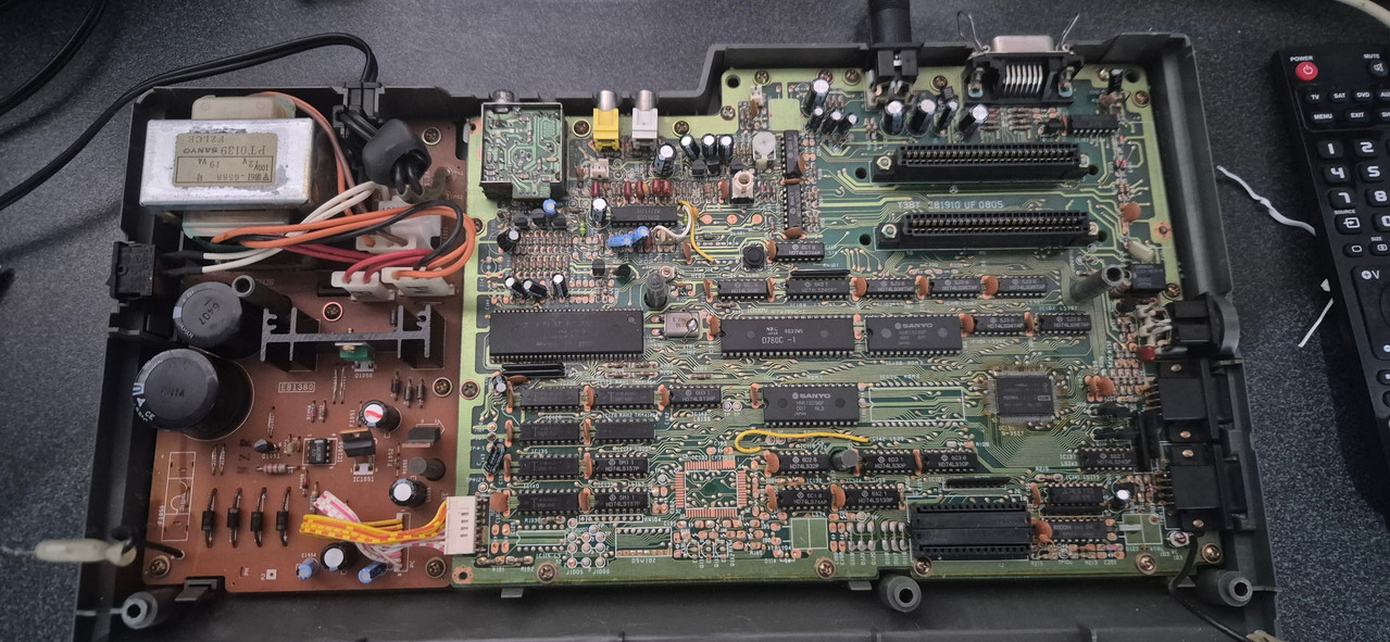
Proving what was still alive#
The power supply cable initially caused some confusion because it measured about 6.3 V, but the regulated rails on the motherboard were correct: +5 V, +12 V and -12 V were all present. The V9938 video processor received 4.97 V, its 21.48 MHz crystal oscillator worked, Reset behaved correctly, and it generated horizontal sync and VRAM timing.
The D780C CPU also had its correct 3.58 MHz clock, a clean Reset signal and activity on its address, data and memory-control lines. This made a completely dead CPU or VDP increasingly unlikely. The grey picture was a consequence of the VDP never being properly initialized, rather than proof that the VDP itself had failed.
One especially useful observation was continuous activity of roughly 689 kHz on the CPU write path, accompanied by very little normal I/O activity. This was compatible with the CPU repeatedly executing invalid ROM data and performing stack writes instead of progressing through the BIOS startup sequence. Attention therefore shifted to IC117, the 32 KiB HN613256P main BIOS mask ROM.
The suspicious BIOS ROM#
I desoldered IC117 and fitted a socket. During removal, one annular ring on pin 10 (A0) and then a trace departing to the left from pin 11 (D0) were damaged, so I repaired that connection with some fine wire before proceeding. This damage was caused during the repair and was not the original fault, however it had to be corrected before the computer could work again.
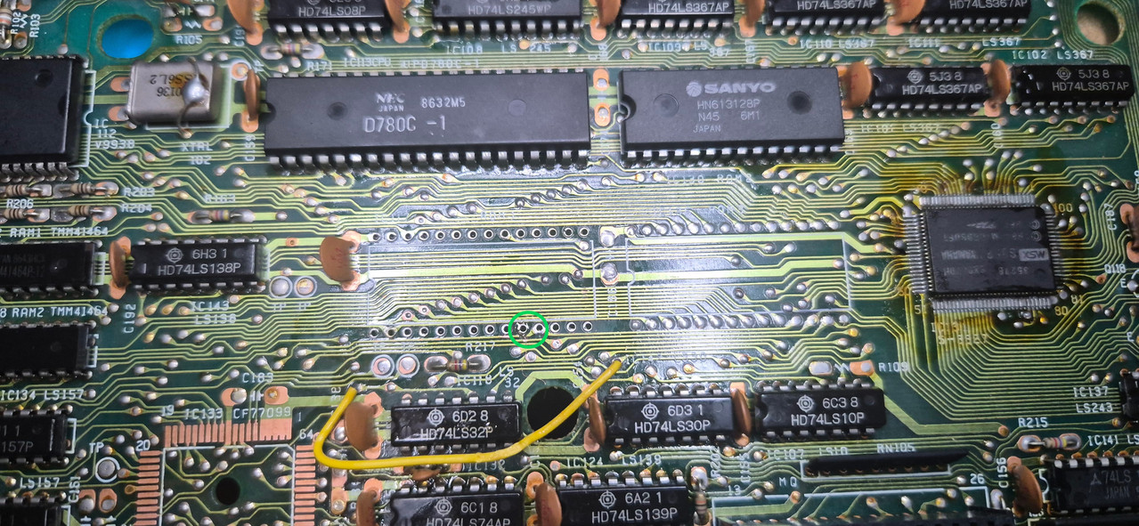
I attempted to read the original mask ROM with a TL866II Plus programmer using a compatible 27256 read profile. The resulting file was the correct 32 KiB size and contained recognizable MSX BASIC code, but parts were plainly corrupted—including Myriosoft where the normal startup text says Microsoft.
Three reads produced three different files. Programmer pin detection also complained about address pins 1, 5 and 6, while analysis showed data repeatedly coming from incorrect A4, A6 and A8 addresses. Some of this instability may have been contact between the old soldered legs and the programmer, so the dumps alone could not conclusively prove the internal failure mechanism.
Fortunately, the exact PHC-23J ROMs were available for comparison (In the MAME repository no less). The verified main BIOS image, 23bios.rom, has this SHA-1 checksum:
4ce41fcc1a603411ec4e99556409c442078f0ecf
It matched the checksum recorded in the openMSX PHC-23J machine definition. The accompanying 16 KiB 23ext.rom also matched the documented MSX2 Sub-ROM, confirming that the reference files were correct.
The replacement#
I blank-checked a 27C256 EPROM, programmed it with the verified 32 KiB 23bios.rom, and read it back into a separate file. The readback matched the source byte for byte and had the same SHA-1 and SHA-256 checksums.
There is one detail worth checking when replacing an HN613256P with a 27C256: pin 1 is unused on the mask ROM but is VPP on the EPROM and must be at +5 V during normal reading. On this Sanyo motherboard, resistance measurements showed that BIOS socket pin 1 was already connected directly to pin 28, the +5 V supply. No adapter or motherboard modification was therefore required. The programmed 27C256 could go directly into the new socket, with its notch facing left.
The result was immediate.
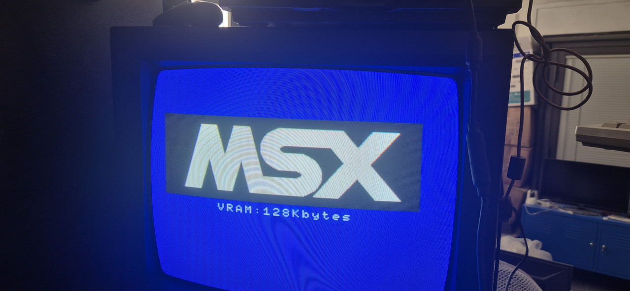
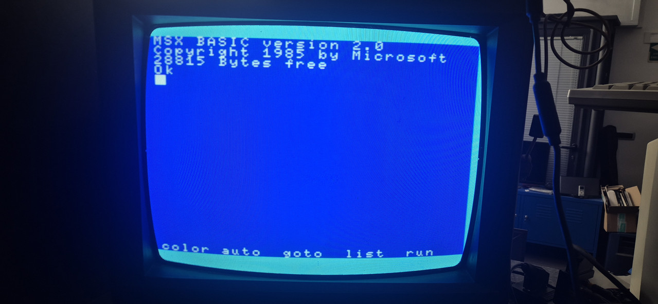
The MSX logo returned, the machine reported VRAM: 128Kbytes, and MSX BASIC 2.0 reached the Ok prompt with 28815 Bytes free.
Final diagnosis#
Replacing the main BIOS ROM restored normal operation. That successful boot also confirmed that the CPU, main RAM, 128 KiB VRAM, V9938 and video-output path were all functioning. The practical diagnosis is a failed IC117 HN613256P main BIOS ROM, although unreliable contact while dumping it prevented us from identifying the exact internal failure.
This repair was a nice example of human and AI collaboration: careful hands and real measurements at the workbench, combined with systematic record-keeping and data analysis. More importantly, a rare MSX2 that initially looked as though it had a dead custom chip is alive again with one socket, one repaired trace and a correctly programmed EPROM.
I realized I was using a power transformer which converts 220V to 110V and not the ideal 100V that Japanese electronics are expecting, so before powering this thing on again I am gonna get one such power adapter.
Safety note: resistance and continuity measurements were made with power disconnected. Oscilloscope measurements used motherboard logic ground. The mains side of the power supply was not probed.